 Mazda 323F GT
Building the exhaust
For those ones who really would like to design and to build the exhaust system themselves and who wants to make the most out of it without paying tons of cash for ready parts. Well to be honest the final result wasn’┐Įt really cheap however need to admit it’┐Įs completely 100% stainless steel (no more bloody rust), 2.5" straight through design. Also the big advantage is you can fix the damaged parts of the exhaust yourself anytime ’┐Į just cut and weld required section, you know how it's been made.
Second thing was kept in mind while constructing this is to maximize the flow ’┐Į the base pipes are 2.5’┐Į (63.5mm, 65mm outside).
The third thing was ’┐Į the final system shouldn’┐Įt be loud. At least it should allow to use it at 6000 revs without causing the first police car at your tail.
The fourth thingy ’┐Į it should be well constructed to be easily mounted and dismounted by yourself at anytime.
And the final requirement was ’┐Į it should be well heat insulated. I am completely fed up with aftermarket systems, which makes gear lever and tunnel looks like a driver boiler. So exhaust been wrapped in insulation from the down-pipe up to the first exhaust box.
To prevent joints from rust the argon welder been used. It’┐Įs not cheap but welding results are impressive ’┐Į smooth and constant.
Original exhaust mounts been used so all hangers been cut from old aftermarket exhaust and welded to the new system. This been done straight on a car to ensure proper system layout been achieved. Part of the exhaust been setup as it should be and corresponding hanger been welded. For some of the hangers the decision was made to make them adjustable. To do this the hangers been welded to the U-clamp (65mm). This makes it possible now to adjust the system setup +- couple of angles and around an inch of move into various directions.
Three bolts flanges (3-flanges, see pics) been used ’┐Į those ones with metal net gasket, which allows few degrees angle setup flexibility between opposing sections of pipes.
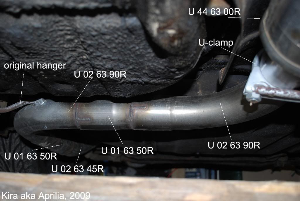
All parts been ordered from Demon-Tweeks so I’┐Įll put p/ns on picture to explain which one goes were.
Most difficult part was a connection of a downpipe to exhaust manifold.
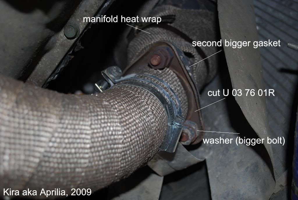
3-flange (p/n U 03 76 01R, part of it with metal net gasket) been modified. Gasket removed, pipe cut, welded and sanded to make front flange surface flat (to connect Mazda exhaust manifold flat three-pin flange). Holes for pins need to be bored out slightly. The tricky thing is a gasket. The original is smaller than it’┐Įs required for the new bigger 2.5’┐Į flange. So compromised solution been implemented ’┐Į two gaskets used. The original gasket goes from the engine manifold side and then a manually cut gasket (just use gasket material to cut gasket of any shape ’┐Į you can get the one from another car, for example) with bigger outer diameter and original smaller inner one.
There is a tight space between the pins and a bigger pipe. Also pins has sections without threading (and new flange is thinner than original one so bolts will not press it) so you can use a thick (1/3 ’┐Į 1/2 inch) washer there (didn’┐Įt have it so just used a bigger bolts).
So the fist flange we’┐Įve created out of three pin flange. Then it goes a 60 deg (U 02 63 60R) section which is welded into flexi pipe p/n CCRBF and then again the 3-flange. Everything perfectly fits in length without need to add any straight pipe section.
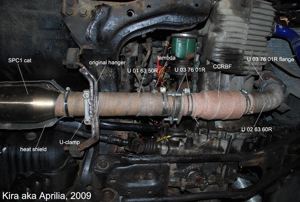
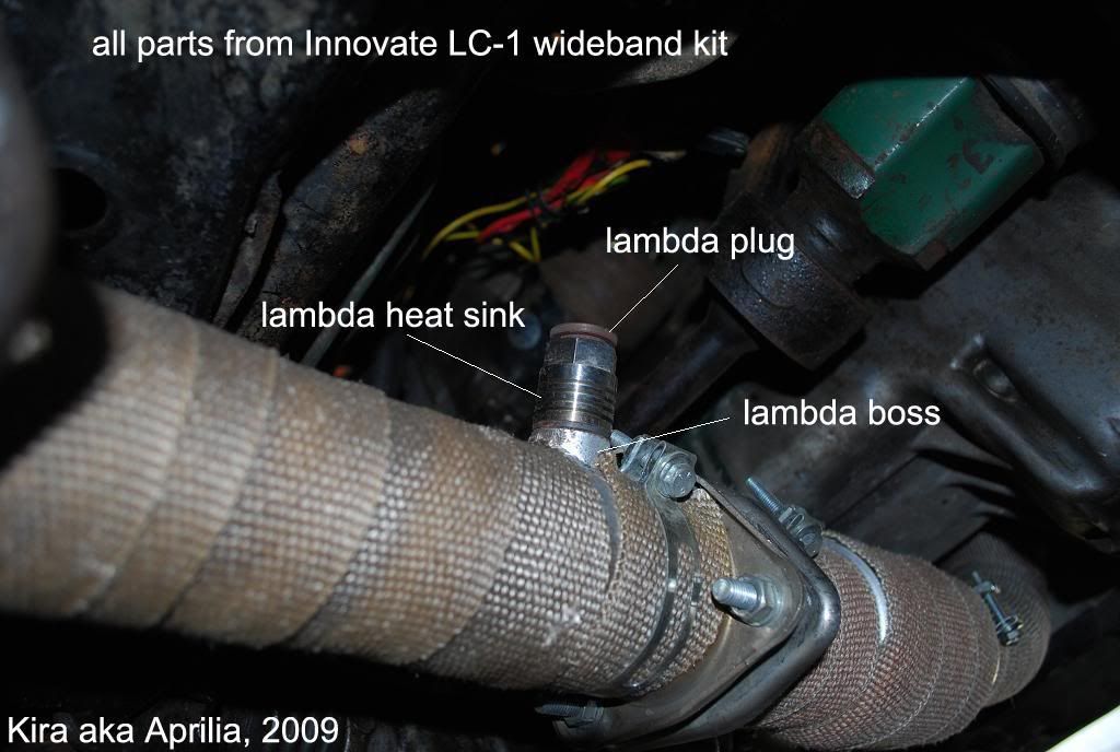
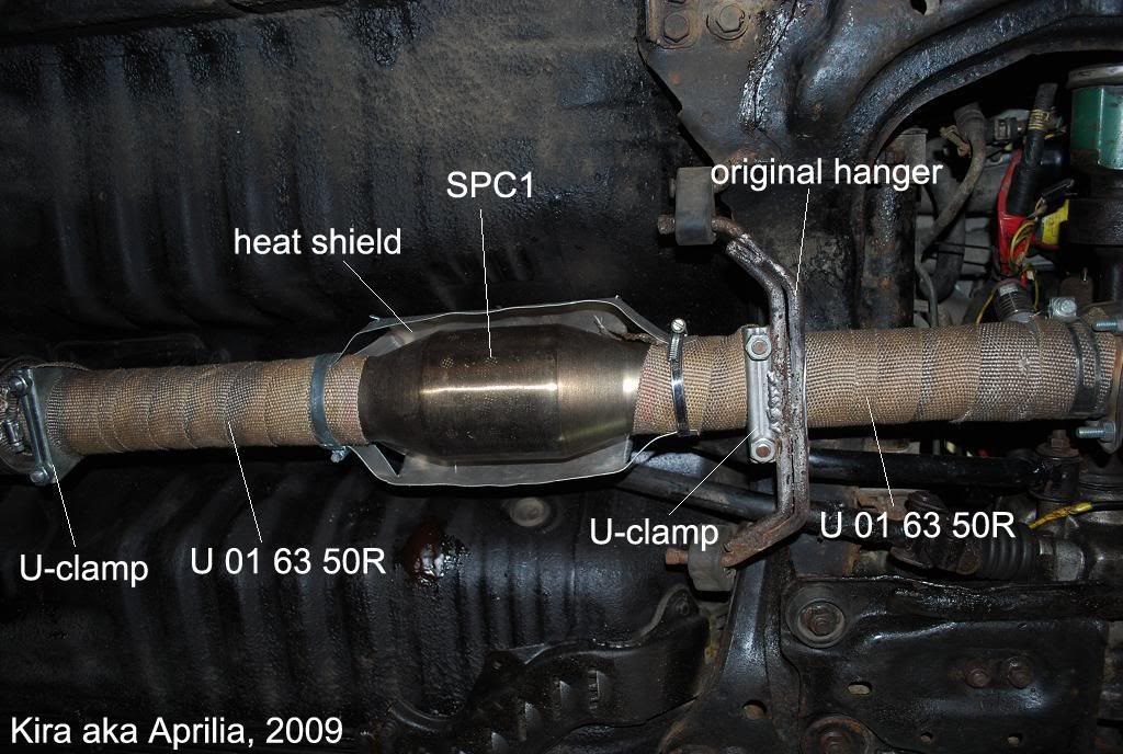
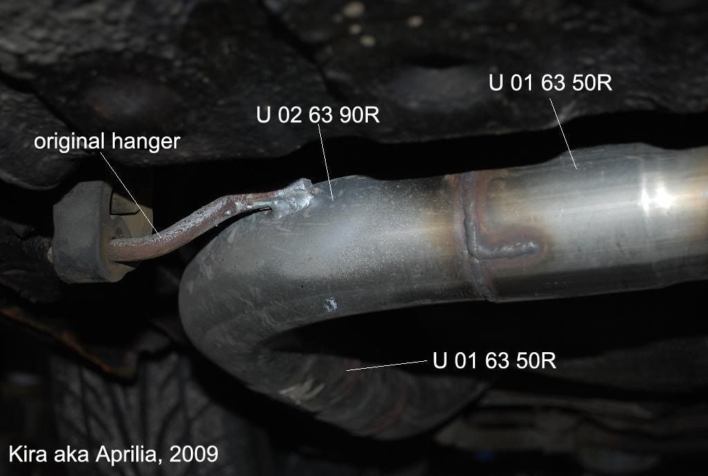
Then it’┐Įs a receiving part of the flange and a straight section of a pipe 500mm (U 01 63 50R) ’┐Į at this section I’┐Įve also installed a lambda boss ’┐Į it’┐Įs for a wideband lambda, with additional heat sink.
This section been mounted using original two side hanger welded to U-clamp.
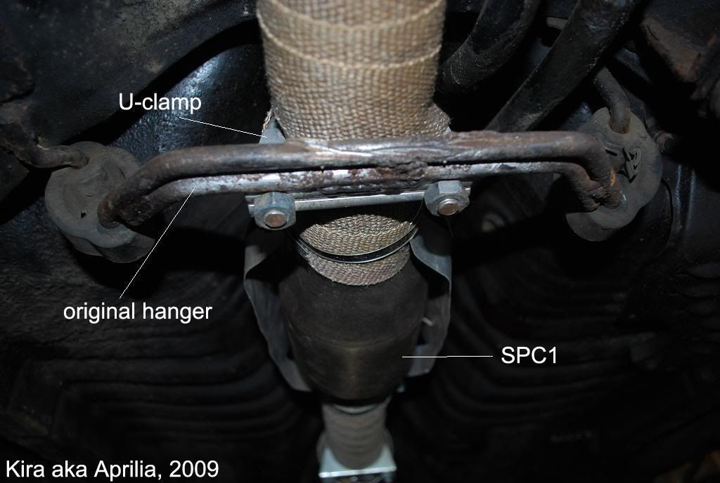
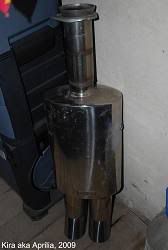
Then it goes the most interesting part. Decided to install a 100 CPSI cat. It’┐Įs not because of MOT or me "going green". Cat (SPC1) itself is ideal to damp the sound from explosion stroke. So it’┐Įs a part of the damping system. It’┐Įs been sold without heat barrier so had to make it myself using thin sheet of aluminum. Cut on a sides few ’┐Įleafs’┐Į and squeeze them to the pipe using clamps (above the wrap layer). Then again goes the section of a straight pipe.
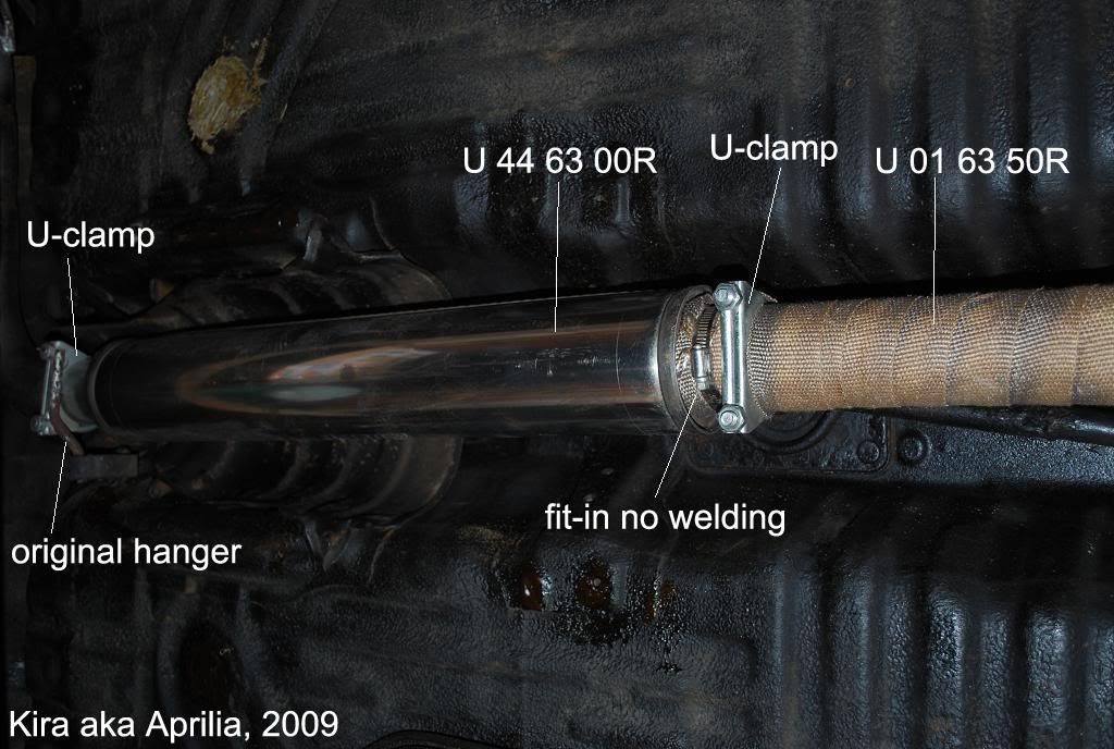
After that it’┐Įs the first (midbox) silencer box (U 44 63 00R Tubex, 625 mm long). Didn’┐Įt weld it to the front section of the exhaust, just connected the pipes and squeeze them using U-clamp ’┐Į this is necessary to make the rear end of the exhaust relatively short to simplify it’┐Įs removal out of the rear axle zone.
There is a hanger welded to the U-clamp after the silencer ’┐Į to adjust the rear end of the silencer (can move U-clamp around the pipe which makes silencer goes up or down a bit).
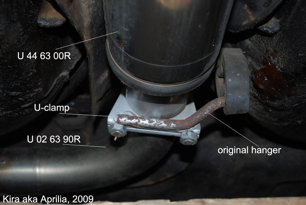
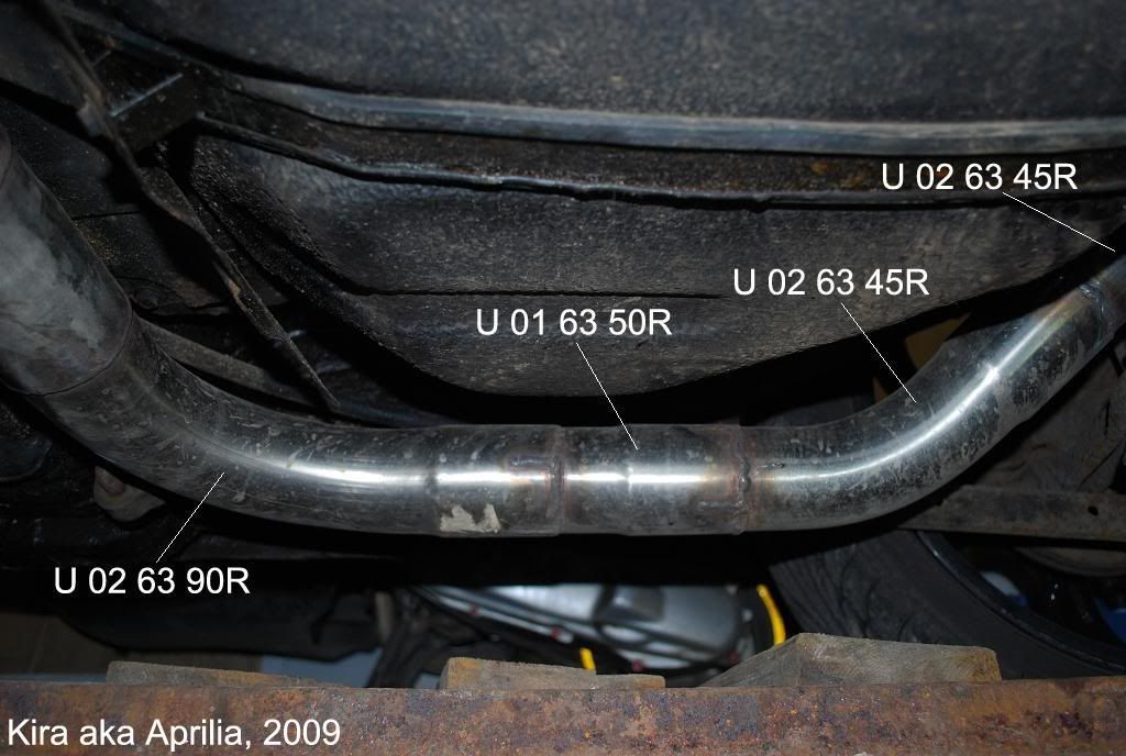
Straight after the silencer there is a 90 deg pipe ( U 02 63 90R), then had to cut a short section of a straight pipe to extend it and then goes second 90 deg turn. Original hanger been welder straight to the pipe at this section.
After it goes again an extension section (using cut from the straight pipe, so in total will need 2 or 3, 500mm straight pipes) and two 45 deg pipes ( U 02 63 45R) one - up and one - down leveling.
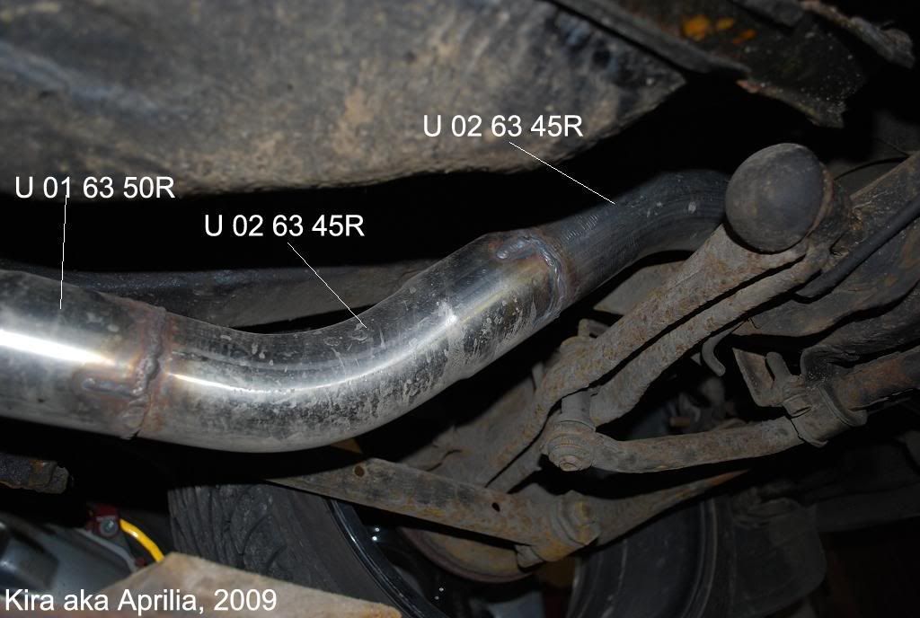
I’┐Įd suggest to weld this section once the front part is complete and setup. You had to carefully adjust all 3D angles to move both bend pipes around the rear axle, with good space to the fuel tank and with exit tip pointing right backward (to be able to install rear silencer correctly). Shake pipes hardly to be sure it will not touch any surroundings before final weld. At the very tip goes 3-flange (straight after the rear axle).
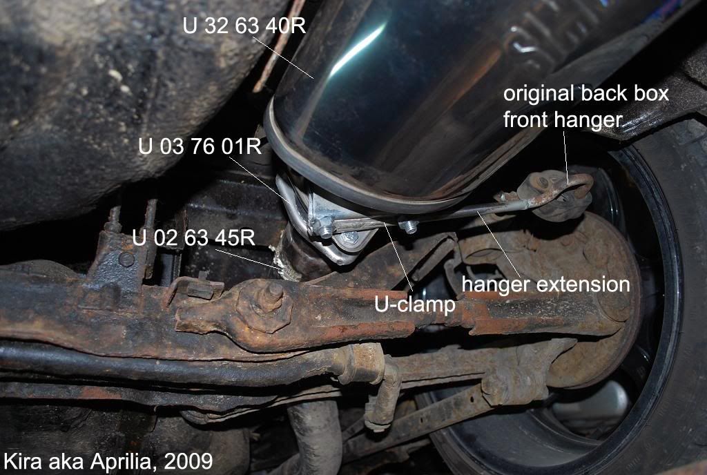
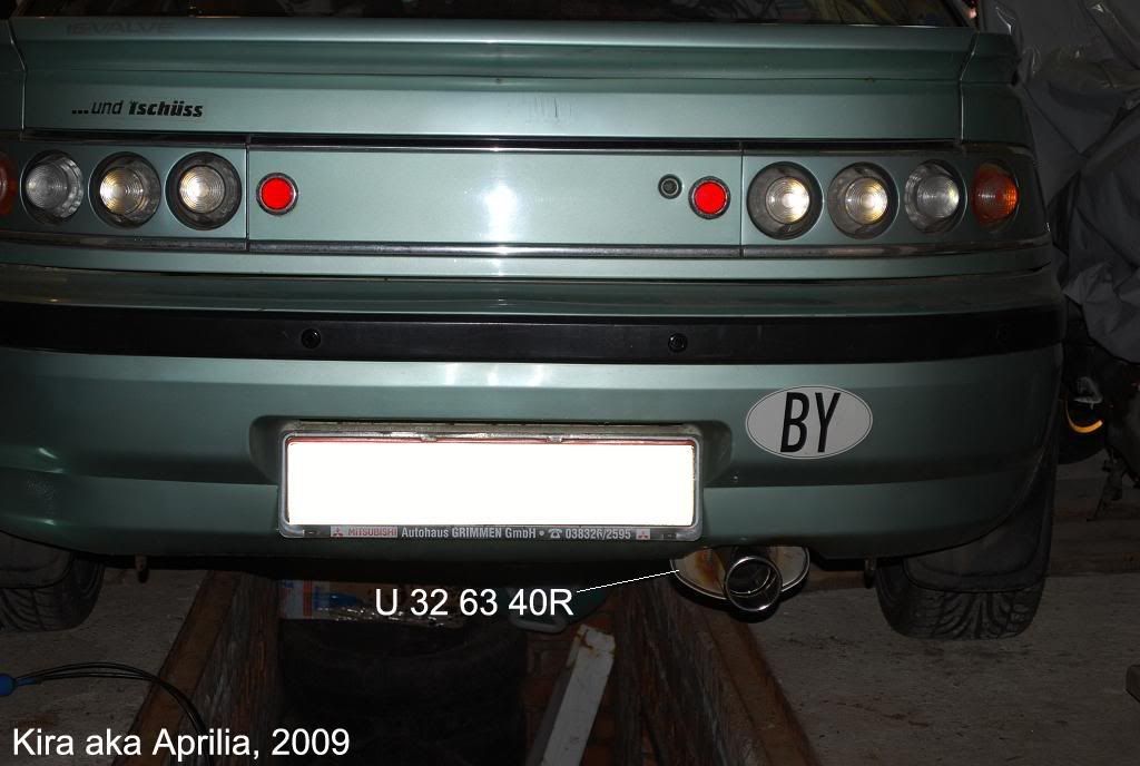
Then goes the rear silencer box (U 32 63 40R) 420mm length. I’┐Įd really install rather a 500 mm box but there is not enough space there for it. Rear box been mounted using hangers cut from the original box (attach the 3-flange first, then stick silencer on it, move it around to position it pointing backward into the center of a notch on a rear bumper, point-weld it to the 3-flange, then weld each of the two back hangers to hold exhaust at the same position, then finish all weldings).
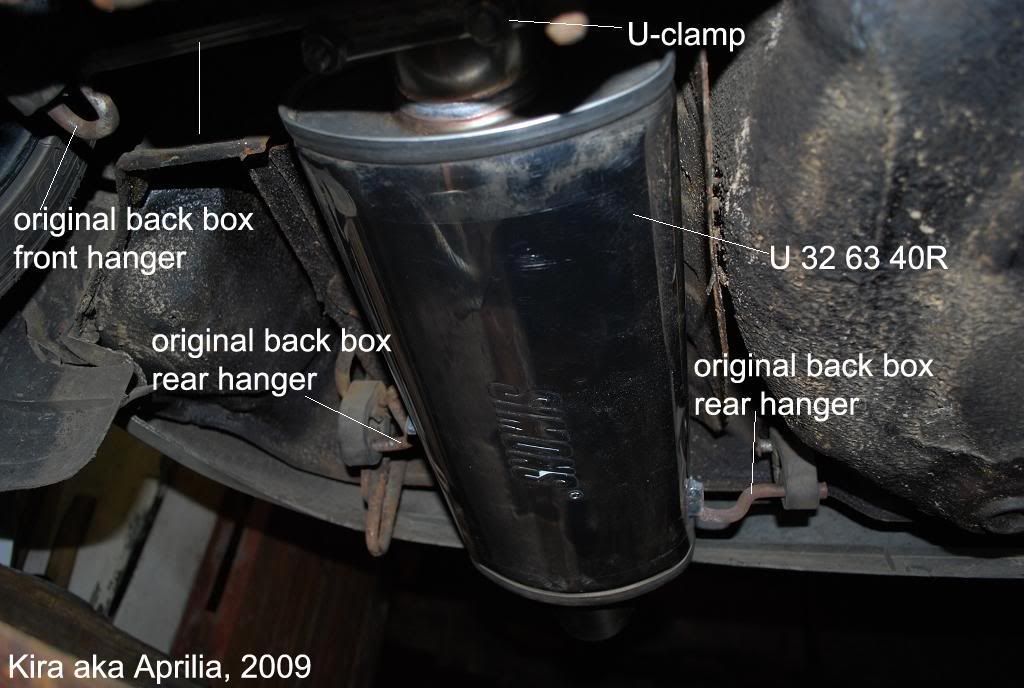
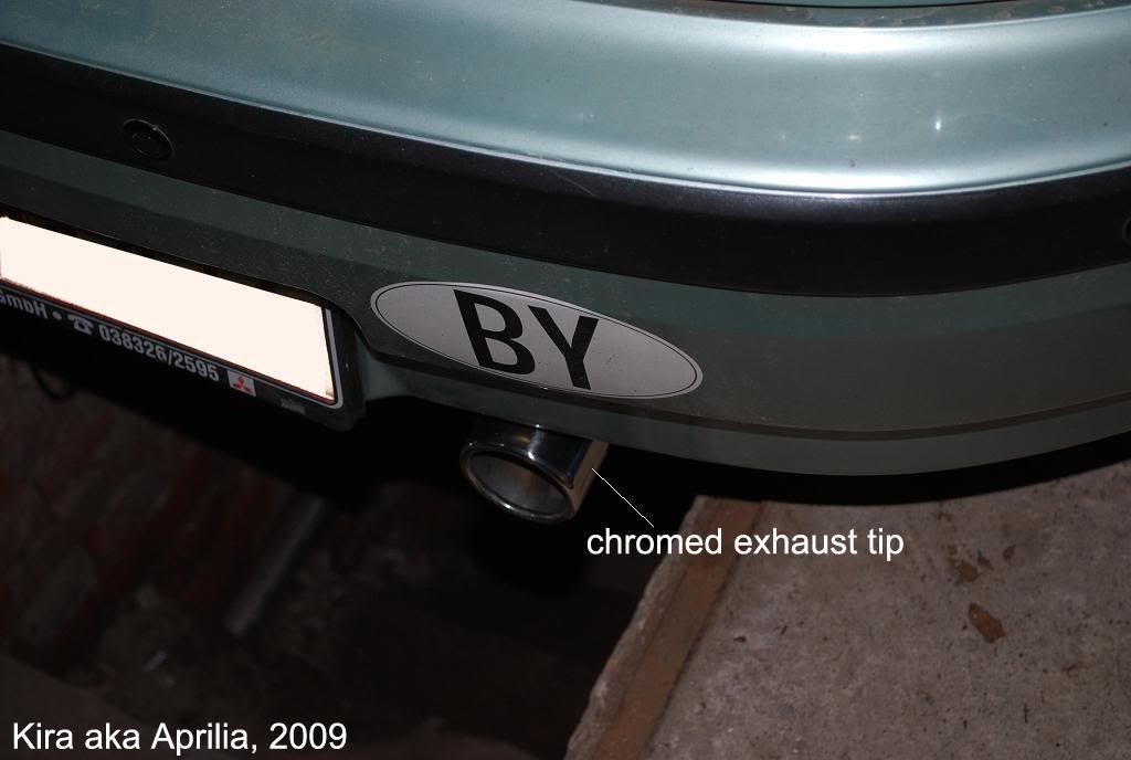
Silencer intake pipe been shortened as much as possible to weld there a receiving part of the 3-flange (it’┐Įs to fit the exhaust as much as possible deep under the body). The front rear-box hanger (with some extension section) been welded to the U-clamp to adjust the rear box position. Then the silencer outer pipe was cut and a chromed shiny tip been welded there to finish the work.
All front section (excluding cat, including exhaust manifold) been covered with exhaust wrap. Now it’┐Įs much better in terms of a heat going inside the tunnel and gear lever. Also radiator fan switching on seldom.
I can’┐Įt remember now how much it did cost me but it should be around 1000USD for the whole system including the work. I’┐Įd say it’┐Įs not cheap at all. But keeping in mind it’┐Įs a complete stainless, when you find your original system ruined by rust, I think it’┐Įs a good choice between a dodgy never-fit-exactly-pen-like-hole-2 years life-crappy systems for the half of those money.
That’┐Įs all.
PS: Now a few tips concerning the boxes. Initial system had only two boxes. The mid one and the back Pro-Sport DTM two-tips box.
God, that was one of a hell loud bloody install. If you look at the whole system you can realize it’┐Įs a complete straight design, 2.5’┐Į and only two free flow boxes separating 7000 revs from the public. What I can say. I’┐Įve managed to drive a car like this for a month. I had to pass the police on a neutral, driving in the city keeping revs always below 2000, and finally had an impression the car got a speed limiter set at 60mph (because it’┐Įs start been painful going quicker). Wasn’┐Įt really a life ’┐Į it was like a thunder at low revs and immediately switching into scream as soon as you floor the pedal. So that’┐Įs why a second version appeared.
First of all initial front straight section been cut and a cat been installed there. Helped a bit to remove those noise peaks. And then the rear box been replaced with the Jetex big one. Now it’┐Įs much much better. It’┐Įs sounds low but not loud. I’┐Įd suggest two boxes as minimum install with rear big one or ideally - a three box install.
Kira
aka Aprilia, 2009